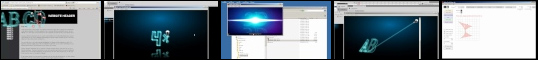
In the component3D.as file these parameters are
defined. If you drag&drop the component to stage,
you can set them through the Component Inspector which
has a custom User Interface for easy understanding.
But if you use addChild methods to generate an instance
of the laser 3D component, you can set them through
actionscript. Below is an overview of which parameter
does what.
| linethickness |
|
Number |
| |
|
The thickness of the 3D shape lines |
| linealphafront |
|
Number |
| |
|
The front alpha transparency of the 3D shape
lines |
| linealphaback |
|
Number |
| |
|
The back alpha transparency of the 3D shape
lines |
| linealphaside |
|
Number |
| |
|
The side alpha transparency of the 3D shape
lines |
| raythickness |
|
Number |
| |
|
The thickness of the laser / lightning ray |
| rayalpha |
|
Number |
| |
|
The alpha transparency of the laser / lightning
ray |
| |
|
|
| blendmodeline |
|
Number (0 = none , 1 = add) |
| |
|
The blendmode type of the 3D shape lines |
| blendmoderay |
|
Number (0 = none , 1 = add) |
| |
|
The blendmode type of the laser / lightning
ray |
| linecolor |
|
hex/number |
| |
|
The color of the 3D shape lines |
| lineglowcolorin |
|
hex/number |
| |
|
The first glow layer (inner) color of the 3D
shape lines |
| lineglowcolorout |
|
hex/number |
| |
|
The second glow layer (outer) color of the
3D shape lines |
| lineglowquality |
|
Number |
| |
|
The glow quality of the 3D shape lines |
| lineglowstrength |
|
Number |
| |
|
The glow strength of the 3D shape lines |
| lineglowalpha |
|
Number |
| |
|
The glow alpha transparency of the 3D shape
lines |
| lineglowblur |
|
Number |
| |
|
The glow blur strength of the 3D shape lines |
| |
|
|
| raycolor |
|
hex/number |
| |
|
The color of the laser / lightning ray |
| rayglowcolorin |
|
hex/number |
| |
|
The first glow layer (inner) color of the laser
/ lightning ray |
| rayglowcolorout |
|
hex/number |
| |
|
The second glow layer (outer) color of the
laser / lightning ray |
| rayglowquality |
|
Number |
| |
|
The glow quality of the laser / lightning ray |
| rayglowstrength |
|
Number |
| |
|
The glow strength of the laser / lightning
ray |
| rayglowalpha |
|
Number |
| |
|
The glow alpha transparency of the laser /
lightning ray |
| rayglowblur |
|
Number |
| |
|
The glow blur strength of the laser / lightning
ray |
| |
|
|
| gridsize |
|
Number |
| |
|
The size of the 3D object |
| griddepth |
|
Number |
| |
|
The depth of the 3D object |
| stretchX |
|
Number |
| |
|
Horizontal stretch/scale of the 3D object |
| |
|
|
| fixed3DrotationX |
|
Number |
| |
|
The fixed/start rotation around axis X of the
3D object |
| fixed3DrotationY |
|
Number |
| |
|
The fixed/start rotation around axis Y of the
3D object |
| fixed3DrotationZ |
|
Number |
| |
|
The fixed/start rotation around axis Z of the
3D object |
| domouseincline |
|
true/false |
| |
|
Rotate the object to mouse movement. Influenced
by
"mouseareaW", "mouseareaH",
"tilthorizontal" and "tiltvertical" |
| doobjectincline |
|
true/false |
| |
|
Rotate the object to object movement. Influenced
by
"mouseareaW", "mouseareaH",
"tilthorizontal" and "tiltvertical"
obs:
(mouseareaW / mouseareaH define the area where
the object is allowed to move within if "objectfollowmouse"
set to false)
|
| mouseareaW |
|
Number |
| |
|
The width of the animation-sensitive mouse
area |
| mouseareaH |
|
Number |
| |
|
The height of the animation-sensitive mouse
area |
| tilthorizontal |
|
Number |
| |
|
The amount to rotate the 3D object horizontally,
if "domouseincline" or "doobjectincline" |
| tiltvertical |
|
Number |
| |
|
The amount to rotate the 3D object vertically,
if "domouseincline" or "doobjectincline" |
| slowrotate |
|
Number |
| |
|
Fixed horizontal rotation per frame |
| autorotate |
|
true/false |
| |
|
Rotate the object once throughout complete
generation period |
| linebyline |
|
true/false |
| |
|
Generates shape lines one by one (instead of
all lines simultaneously) |
| linebuildsteps |
|
Number |
| |
|
Number of frames it takes to build each line
of a shape |
| delaytime |
|
Number |
| |
|
Number of seconds to wait with fully created
object before going to the next one in sequence |
| outsteps |
|
Number |
| |
|
Number of frames it takes to remove the object
(all lines decrease/shrink simultaneously) |
| |
|
|
| usesource |
|
Number |
| |
|
Use a source for the laser / lightning ray
to start from |
| |
|
|
| beam |
|
String ("laser"
or "ray") |
| |
|
The method creating the shapes coming out of
the gun, either "laser" or (lightning)
"ray" |
| frommouse |
|
true/false |
| |
|
Decides if the laser is glued to the mouse
cursor or not |
| fromobject |
|
true/false |
| |
|
Decides if the laser object (gun) is added/used
or not |
| gunminscale |
|
Number |
| |
|
Laser gun minimum scale |
| gunmaxscale |
|
Number |
| |
|
Laser gun maximum scale |
| objectfollowmouse |
|
true/false |
| |
|
Decides if the laser object (gun) chases the
mouse position or if it flies around randomly
on its own |
| fixedpoint |
|
true/false |
| |
|
Decides if a fixed point of origin is used
or not |
| fixedpointX |
|
Number |
| |
|
The horizontal fixed point of origin |
| fixedpointY |
|
Number |
| |
|
The vertical fixed point of origin |
| singleplane |
|
true/false |
| |
|
Decides if only the front side of the 3D object
should be used/created |
| connectall |
|
true/false |
| |
|
Decides if the front side points should all
be connected to one point (if "singleplane"
set to true) |
| noray |
|
true/false |
| |
|
Decides if the generating laser / lightning
ray line should be used or not (if "singleplane"
set to true) |
| |
|
|
| addsmoke |
|
true/false |
| |
|
Decides if smoke particles should come from
the point where the laser is drawing |
| addsparks |
|
true/false |
| |
|
Decides if spark particles should come from
the point where the laser is drawing |
| intervalsmoke |
|
Number |
| |
|
Interval in frames between generation of smoke
particles |
| intervalsparks |
|
Number |
| |
|
Interval in frames between generation of spark
particles |
| sparktype |
|
Number (1,2 or 3) |
| |
|
The type of sparks it should generate:
1) Basic short hot sparks
2) Fusing smooth sparks
3) Heavier welding hot sparks
|
| |
|
|
| addmirror |
|
true/false |
| |
|
Decides if a mirror reflection should be generated |
| mirrorgun |
|
true/false |
| |
|
Decides if the laser object (gun) should also
be reflected |
| mirrorscale |
|
Number |
| |
|
The vertical scaling of the reflection |
| virtualfloor |
|
Number |
| |
|
The thickness of the 3D shape lines |
| reflectionheight |
|
Number |
| |
|
The height of the reflection (the bottom distance
where it will be 0% transparent) |
| watermirror |
|
true/false |
| |
|
Reflect the 3D object as water surface |
| |
|
|
| xmlfile |
|
String |
| |
|
The xml file name to use, in case of "inputtype"
1 (xml) |
| auto3D |
|
true/false |
| |
|
Automatically generate 3D animation from 2D
shape data
NOTICE: The component actually is able to receive
3D data from class or xml file (try the icosa
as shape name and set "auto3D"
to false). At this current moment it's not likely
you'll need it but in case you do have methods
to generate 3D data containing Vertices definition
and faces definitions, you'll actually be able
to use those. In the future it may be possible
to extract those from 3rd party applications like
3D max or Swift 3D or maybe papervision or other
solutions, so when that moment comes you'll be
able to hook up your 3D creations into this precreated
method. |
| aspreloader |
|
true/false |
| |
|
Set the 3D animation to function as preloader.
Don't forget to push the preloading % value to
variable "fr"
of the component instance. This method uses "pixel_simple"
shape inputs (see function genobj() in
component3D.as) |
| glyphstring |
|
String |
| |
|
The string of shapes to be used [shape1A, shape1B]
, [shape2A, shape2B ,shape2C] , [shape3A]
[example_shape, star]
, [doublestar, SPACE,SPACE,SPACE, example_shape]
, [serif_a, sans_a] , [FONT_SERIF_abc, FONT_SANS_abc]
The above example will do the following
sequence 1) combo example_shape
+ star
sequence 2) combo doublestar
+ example_shape
and adds SPACE's
inbetween (1 grid unit empty shape)
sequence 3) combo serif_a
and sans_a
sequence 4) combo serif_a
and serif_b and
serif_c
and sans_a
and sans_b
and sans_c
|
| inputtype |
|
Number (0,1 or 2) |
| |
|
Inputtype of the component
1) class
2) xml
3) drawing panel
Notice it's possible to actually use 3) drawing
panel when you use addChild to generate instances.
You can't draw anything that way and you'll still
need to push appropriate strings to the 4 parameters
below. You'll at least once need to use the drawing
panel in the component instance to generate the
data, but you can use trace() in the actionscript
file (component3D.as) to trace out what you drew
and save that result on some txt file on your
computer and then you can later push that data
when using addChild. Obviously recommended would
be exporting to class or xml code and using that
method instead. But there are cases where this
method could prove useful
|
| |
|
|
| drawapp_string_grid |
|
String |
| |
|
Combination of drawing app grid settings |
| drawapp_string_pts |
|
String |
| |
|
Combination of drawing app grid settings points
data |
| drawapp_string_sds |
|
String |
| |
|
Combination of drawing app grid settings shape
sides data |
| drawapp_string_sdscurveto |
|
String |
| |
|
Combination of drawing app grid settings shape
curveto sides data |